Loudspeakers. Brackets. Backing.
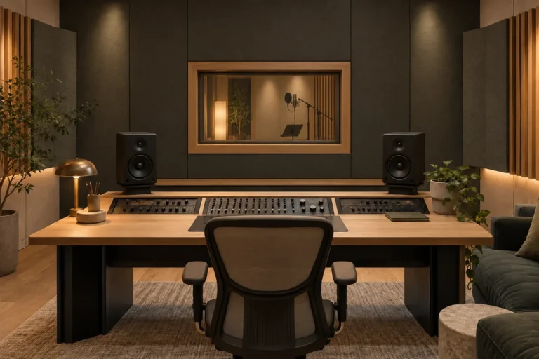
Plan the loudspeaker and its mount into the decoupled structure. Use suitable reinforcement and a defined path to the clips, rather than treating the plasterboard as the support.
FluxCore™ Built for the hard part
Discover The FluxCore Effect: multi-density decoupling with load-bearing steel construction. Designed around layered walls, ceilings and project-engineered equipment mounts. Mechanical testing of the clip and channel, and acoustic testing of the complete wall, by SINTEF.

01 See the principle
A softer inner core. A firmer outer core. A different approach to the connection between a room and its structure. Watch the FluxCore film, then explore the measured performance of the complete wall system.
01 / Decouple
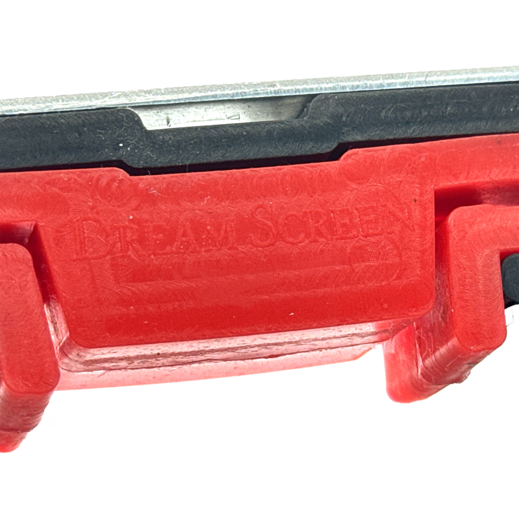
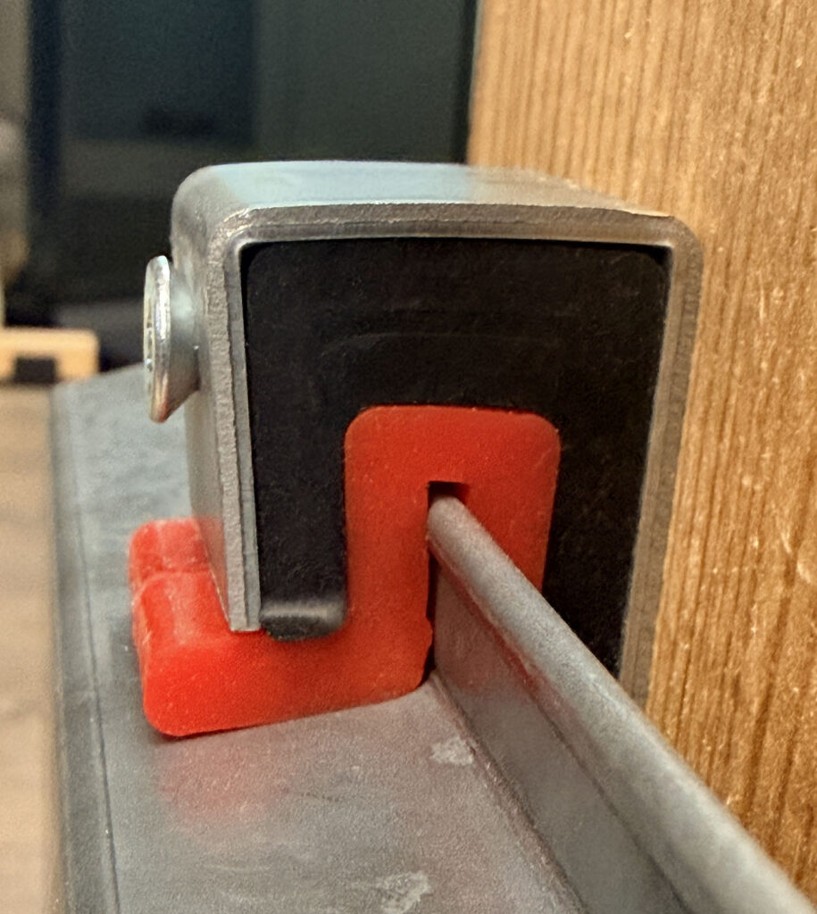
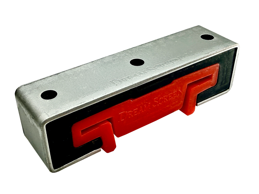
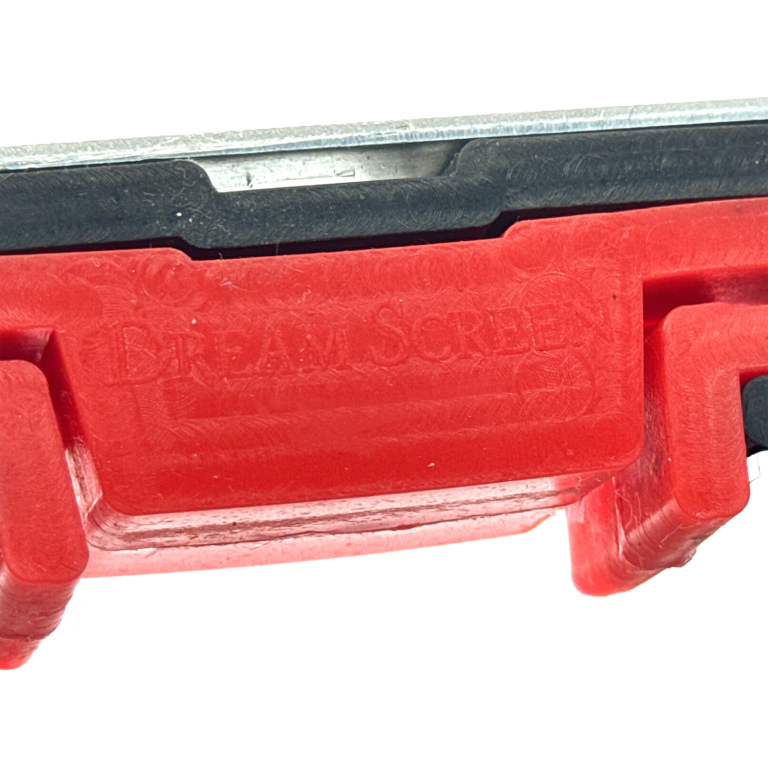
FluxCore combines two elastomer cores in the mechanical connection supporting the lining. The softer inner core works within a firmer outer core.
02 / Measure
The complete ProSilence wall was measured in SINTEF's laboratory. Explore the sound reduction at each low-frequency band below.
03 / Build
Connect the clips, channels, floor supports, damping compound and supporting materials in the System Planner.
ENGINEERED TO SUPPORT The load-bearing side of FluxCore
Soft core. Serious support. FluxCore pairs multi-density decoupling with a load-bearing steel clip. Use the capacity for substantial board mass and additional local equipment loads — from studio loudspeakers to private-cinema installations. Fewer clips where suitable. More load headroom where it matters.
Calculated permissible ceiling load with safety factor 2.5 — about 48.4 kg mass equivalent. Mean laboratory failure load: 1,503.5 N. Wall shear has separate 350 N guidance for intended decoupling function.
STUDIOS + PRIVATE CINEMAS Beyond evenly distributed board weight
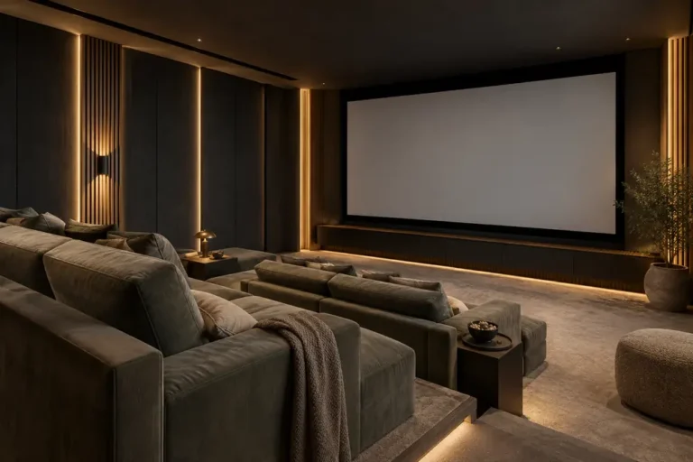
Higher capacity at each clip is not only about using fewer clips. It also creates useful load headroom for substantial ceiling linings, projector mounts, Atmos speakers and other equipment carried by a properly designed isolated structure.
Put the capacity where the room needs it.
Plan the loudspeaker and its mount into the decoupled structure. Use suitable reinforcement and a defined path to the clips, rather than treating the plasterboard as the support.
Build equipment loads into the ceiling design from the start. The 475 N figure is the SINTEF-derived permissible load for the tested clip/channel ceiling orientation; anchors, backing, leverage and any required secondary restraint still need their own checks.
Allow for fixtures and local weight concentrations, not just the lining. The clip layout can be reinforced locally while preserving the intended isolated mounting concept.
PER-CLIP LOAD BUDGET / CEILING EXAMPLE
For this comparison only, every clip supports 0.36 m² at 30 kg/m²: 10.8 kg of uniformly distributed ceiling lining load. A common 600 × 600 mm grid isolates the per-clip capacity comparison from the separate wall-spacing example below.
Load-budget illustration, not a rated point load. Reserve at one clip is not a permissible loudspeaker weight, and reserves cannot simply be added to rate a mount. Bracket leverage, unequal load sharing, channels, backing, anchors and dynamic forces govern the actual equipment design. The sources use different load definitions; this is not a matched load test.
CEILING CAPACITY + WALL GUIDANCE
For ceiling pull-out, SINTEF calculated a permissible load of 475 N per clip using a 2.5 safety factor — approximately 48.4 kg mass equivalent. The mean laboratory failure load was 1,503.5 N. This is the relevant headline capacity for suspended ceilings and overhead equipment planning.
Wall shear behaves differently. There, the draft report recommends limiting load to 350 N (about 35.7 kg mass equivalent) with the intended decoupling function in mind, based on deformation behaviour. Neither figure is an acoustic rating at that load.
The 30 kg/m² supported mass is an illustrative design input, not the measured weight of a named ceiling. The common 600 × 600 mm field gives 10.8 kg per clip. FluxCore ceiling: 475 N ÷ 9.80665 = approximately 48.44 kg mass equivalent; arithmetic reserve approximately 37.64 kg in this illustration. IsoMax: 36 lb × 0.45359237 = 16.3293 kg with 25 ga channel, leaving 5.5293 kg arithmetic reserve; 48 lb = 21.7724 kg with 22 ga channel, leaving 10.9724 kg. Both plotted IsoMax values use the manufacturer's 2.5:1 safety-factor column. Its alternative 2:1 column gives 45 lb (20.4117 kg) and 60 lb (27.2155 kg), respectively. Each 16 kg comparator limit gives 5.2 kg arithmetic reserve. MuteClip's separate 12 kg planning target gives 1.2 kg reserve. Rounding is for display only.
FluxCore source: SINTEF PR26-00288, version 01, 14 August 2026. For ceiling pull-out, the report calculates 475 N permissible load with safety factor 2.5 from a mean laboratory failure load of 1,503.5 N. For wall shear, the report separately recommends 350 N with the intended decoupling function in mind, based on deformation behaviour. Neither value is an acoustic measurement at that load. The complete wall's low-frequency measurements were made separately and do not establish unchanged acoustic performance at every equipment load or a tested acoustic advantage over competing clips under concentrated loads.
IsoMax source: Kinetics installation guidelines, page 2, published by Kinetics Group. The capacity depends on channel gauge and is calculated from tests in which the channel deforms and pulls out; it is not a separate limit established by acoustic testing. Kinetics lists the same design-load table for wall shear and ceiling tension. The 2.5:1 factor is suggested for more critical life-safety applications; the manufacturer also lists 2:1 values. Its maximum spacing is 48 inches along channels and 24 inches between channels, subject to the load and installation requirements. The 600 × 600 mm illustration above is a common comparison grid, not an IsoMax installation prescription. Neither load row is asserted to be the specific gauge of acoustic test AT001058.
Kinetics IsoMax: original installation and load table, page 2 ↗
MuteClip: manufacturer maximum load and 75% planning guidance ↗
GenieClip RST: manufacturer maximum design load ↗
Higher per-clip capacity can be allocated to spacing or to additional local loads; it cannot be counted twice. The System Planner provides a material and layout starting point, not an engineered equipment-mount rating.
THE CAPACITY ADVANTAGE / MADE VISIBLE
See what greater capacity per clip can enable. This example compares a 600 × 1,200 mm FluxCore layout with MuteClip's published 600 × 600 mm stud-wall grid — before perimeter and detail requirements.
PLANNING EXAMPLE
600 mm between rows × 1,200 mm along each row. ProSilence planning example; confirm the selected boards, channels, anchors and loads.
PUBLISHED STUD-WALL GRID
600 mm between rows × 600 mm along each row. iKoustic stud-wall installation guide, January 2026, pages 2–3.
Four rather than eight isolation points carry the same illustrative mass. Fewer clip units to place where the construction allows — not a claim of 50% lower project cost, installation time or better acoustic isolation.
These are repeating sections of a larger wall, not two complete wall installations. Boundary clips, openings, joints and concentrated loads can change the final count. The assumed mass includes everything carried by that lining; it is not the measured weight or acoustic result of a specific assembly.
THE LOAD BEHIND THE LAYOUT
FluxCore / primary ceiling rating
475 N≈48.4 kg mass equivalentSINTEF calculated permissible ceiling load with safety factor 2.5. Separate wall guidance is 350 N (≈35.7 kg) for intended decoupling function. Neither is a separate acoustic rating at that load.
MuteClip / manufacturer limits
16 kg maximum12 kg planning targetiKoustic aims for no more than 75% of its published maximum load. Neither figure is a measured failure load.
GenieClip RST / manufacturer limit
16 kg per clip600 × 1,200 mm standard spacingPliteq also publishes the wider spacing. The distinction here is capacity per clip, not a claim that every competitor uses a denser grid. Spacing must suit the chosen lining weight.
Different source definitions and test bases are shown explicitly; this is not a matched load test. No remaining capacity is being promised for a speaker or projector at a single board fixing. Equipment loads need suitable backing, distribution and project-specific design.
Calculation: area per clip = row spacing × spacing along the row; clip density = 1 ÷ area per clip; illustrative load per clip = 30 kg/m² × area per clip. Rounding is for display only. The 2.4 × 1.2 m repeating field contains 4 clips at 600 × 1,200 mm or 8 clips at 600 × 600 mm.
FluxCore: the illustrated grid is a ProSilence planning assumption, not a universal board-manufacturer approval or an additional SINTEF test. The load recommendation is from SINTEF PR26-00288, version 01, 14 August 2026. Read the full distinction between failure load, strength-based permissible load and intended-function load below.
MuteClip installation guide / stud walls, pages 2–3 ↗
MuteClip manufacturer FAQ / maximum and planning load ↗
GenieClip RST manufacturer FAQ / load and standard spacing ↗
Source check: 17 September 2026. Capacities are per clip in the specified use, not the load capacity of the complete wall, its channels, its backing or an arbitrary equipment fixing. Comparison is for regular wall fields, not ceilings.
Design multi-layer gypsum-fibre linings as a complete load-bearing assembly. Select the number and spacing of clips for the board weight, compound and finish.
Include speakers, projector mounts and other equipment in the load plan. Use suitable backing, fasteners and additional clips where concentrated loads require them.
Design the mount into the decoupled structure rather than unintentionally bridging it. Check the complete connection, not the clip alone.
Equipment mounting requires project-specific design for total load, local load distribution, leverage, backing and anchors. A per-clip figure is not a permissible load on an arbitrary screw in a gypsum board, and the board weight already uses part of the system capacity.
SINTEF PR26-00288, version 01, 14 August 2026: four samples in each orientation. The test results below are from the available draft report. Mechanical capacity and acoustic behaviour under load are different questions.
| Result / load basis | Ceiling orientation | Wall orientation |
|---|---|---|
| Mean laboratory failure load | 1,503.5 N | 1,485.5 N |
| Calculated permissible load, safety factor 2.5 | 475 N About 48.4 kg mass equivalent | 543.5 N About 55.4 kg mass equivalent; see functional limit below |
| Report recommendation for intended acoustic function | Acoustic performance at the 475 N load was not assessed in this mechanical test. | Limit to 350 N About 35.7 kg mass equivalent; recommendation based on deformation behaviour, not a separate acoustic test at this load |
Failure loads are not working loads. On walls, the report's 350 N recommendation takes precedence over the higher strength-based calculation when preserving the intended decoupling function. The report calls for each installation to be designed individually.
Selected competitor reference: Pliteq publishes a maximum design load of 16 kg for GenieClip RST. iKoustic publishes a maximum of 16 kg for MuteClip and recommends planning below 75% of that maximum. These are manufacturer load definitions, not results of the same test method or evidence that either product fails at 16 kg. No ratio of break strength to a competitor's working load is presented.
GenieClip RST product specification / maximum design load ↗
MuteClip manufacturer guidance / load and operating margin ↗
02 Understand the measurements
Measured in the laboratory. Presented by frequency. Explore the 50–80 Hz sound reduction of the complete ProSilence wall, then compare it with named clip-based constructions and their total wall thickness.
MEASURED PERFORMANCE / NOT A SIMULATION
Complete wall assembly
ISO 10140-2 · 25 August 2026
Sound reduction index R. Laboratory measurements of the tested wall — not a clip-only improvement value.
Total wall thickness: outer finished face to outer finished face, including both board packs, the frame and the decoupled lining. Not the clip depth or added lining alone.
SINTEF 102036124-2-1
182 mmTOTAL WALL THICKNESSNominal total from the corrected ProSilence build-up
98 x 48 mm timber studs (98 mm wall depth) + four 12.5 mm gypsum-fibre boards + 34 mm clip offset on one side = 182 mm.
Provisional SINTEF wall measurement
AT001058 / RAL TL02-40
187 mmTOTAL WALL THICKNESSReported total wall thickness
One 2 x 4 timber frame; two 5/8-inch boards per side; clips on one side.
50-80 Hz: unofficial development data
Timber wall / source page 11
Approx. 184 mmTOTAL WALL THICKNESSCalculated total, not a measured total
95 mm timber frame; one 15 mm board opposite two 15 mm boards and Tecsound.
Published R/Rw table; metric notation to clarify
TL07-670 / timber wall
197 mmTOTAL WALL THICKNESSManufacturer nominal total wall thickness
One timber frame; two approx. 16 mm boards per side; clips on one side.
Published test-reference data; 80 Hz point only
Selected complete walls, not a ranking of every configuration sold under each brand. Missing 50 and 63 Hz GenieClip values are left blank, not inferred. IsoMax low-frequency development data is not presented as equivalent to the published laboratory rating. ProSilence nominal total wall thickness is 182 mm: 98 mm frame + 50 mm of boards + 34 mm clip offset. The selected clip-based walls have comparable overall depths; no substantial space-saving advantage is claimed. All thicknesses refer to complete wall constructions.
31.3 dB for the SINTEF-measured ProSilence wall versus 23.3 dB in MuteClip Double's published timber-wall table. Different complete assemblies; see construction and source details.
38.4 dB for the SINTEF-measured ProSilence wall versus the published 31.0 dB for GenieClip RST, test TL07-670. A comparison of complete assemblies, not clips in isolation.
98 mm timber framing + four 12.5 mm boards + 34 mm clip offset. Comparable in depth to the selected clip-based walls; the focus is low-frequency performance and load-bearing design, not a substantial thickness advantage.
Measured in the laboratory, not simulated. ProSilence values are from SINTEF data sheet 102036124-2-1, 25 August 2026, marked “PROVISIONAL DATA SHEET / INTERNAL USE ONLY”. The laboratory measurements are complete. The formal report is pending. The corrected nominal wall thickness is 182 mm: 98 mm timber framing + four 12.5 mm gypsum-fibre boards + 34 mm clip offset on the isolated side. This replaces the earlier 150 mm figure; the acoustic measurement values are unchanged. The measured acoustic figures are not simulations or estimates. These measurements apply to the tested wall, not every room calculated below or a floating floor.
| Tested wall | Total wall thickness | 50 Hz | 63 Hz | 80 Hz | Source status |
|---|---|---|---|---|---|
| ProSilence FluxCore SINTEF 102036124-2-1 | 182 mm Nominal total from the corrected ProSilence build-up | 26.1 | 31.3 | 38.4 | Provisional SINTEF wall measurement |
| Kinetics IsoMax AT001058 / RAL TL02-40 | 187 mm Reported total wall thickness | 24.0 | 30.0 | 36.0 | 50-80 Hz: unofficial development data |
| MuteClip Double Timber wall / source page 11 | Approx. 184 mm Calculated total, not a measured total | 22.1 | 23.3 | 24.4 | Published R/Rw table; metric notation to clarify |
| GenieClip RST TL07-670 / timber wall | 197 mm Manufacturer nominal total wall thickness | — | — | 31.0 | Published test-reference data; 80 Hz point only |
ProSilence: SINTEF 102036124-2-1, test date 25 August 2026, marked provisional/internal use only. The manufacturer-corrected nominal build-up is 98 mm timber frame + four 12.5 mm gypsum-fibre boards (50 mm total) + 34 mm clip offset on the inside = 182 mm. This replaces the earlier 150 mm figure, which omitted the clip offset. The dimension is calculated from the stated component sizes; the unchanged acoustic values come from SINTEF laboratory measurements.
IsoMax AT001058: one 2 x 4 timber stud frame, two 5/8-inch boards on each side, IsoMax and furring channels on one side. The source review of 10 September records 187 mm total thickness from Kinetics/Riverbank RAL TL02-40. Its STC 64 laboratory rating is distinct from the unofficial 50-80 Hz development figures shown here. The original source and suitability for external comparative use must be rechecked before publication. This is not the deeper AT001090 assembly.
MuteClip Double: approximately 184 mm is a calculated total: 95 mm frame + 15 mm opposite board + 74 mm published system lining. It is not a measured overall dimension in the acoustic sheet. The treated assembly lists two 15 mm boards and Tecsound on the clip side, with one 15 mm board opposite. The sheet mixes R/Rw notation with a standardized-level-difference subtitle; the original report must resolve this before a final comparative claim.
GenieClip TL07-670: Pliteq gives 197 mm nominal total depth for its timber wall with two approximately 16 mm boards per side. The brochure publishes 31 dB at 80 Hz and 39 dB at 100 Hz, but no 50 or 63 Hz values for this assembly. Only the 80 Hz point falls in this graph. Missing data is not evidence of poor performance or absence of laboratory testing.
Kinetics: IsoMax assembly and report references ↗
Kinetics: supplementary low-frequency source ↗
iKoustic: performance sheet, page 11 ↗
iKoustic: 74 mm lining-depth specification ↗
Pliteq: construction and results, printed pages 14 and 20 ↗
The homepage is deliberately limited to 50-80 Hz; the linked source material is not truncated. Knauf upgraded walls and the 254 mm IsoMax AT001090 wall are outside this initial comparison. Adding two further 12.5 mm boards on the stiff side would make a nominal 207 mm wall (182 + 25 mm), with two layers on the isolated side and four on the stiff side. This proposed assembly is not represented by the current acoustic curve; a future test must have its own results, date, layer schedule and measured thickness.
SINTEF measured the complete wall according to ISO 10140-2. The overall result is Rw (C; Ctr) = 61 (−1; −5) dB. The measured wall, the planner's room and the individual components are different scopes; no automatic acoustic rating is assigned to the planner output.
| Frequency / Hz | Sound reduction R / dB | Qualifier |
|---|---|---|
| 50 | 26.1 | Provisional measured value |
| 63 | 31.3 | Provisional measured value |
| 80 | 38.4 | Provisional measured value |
Values below 50 Hz are not supplied by this table. No estimated sub-50 Hz points are added.
03 The core of the system
Explore the components at the heart of ProSilence, then build the supporting layers around them. The System Planner connects both in one practical project schedule.

Walls + ceilings / Decouple
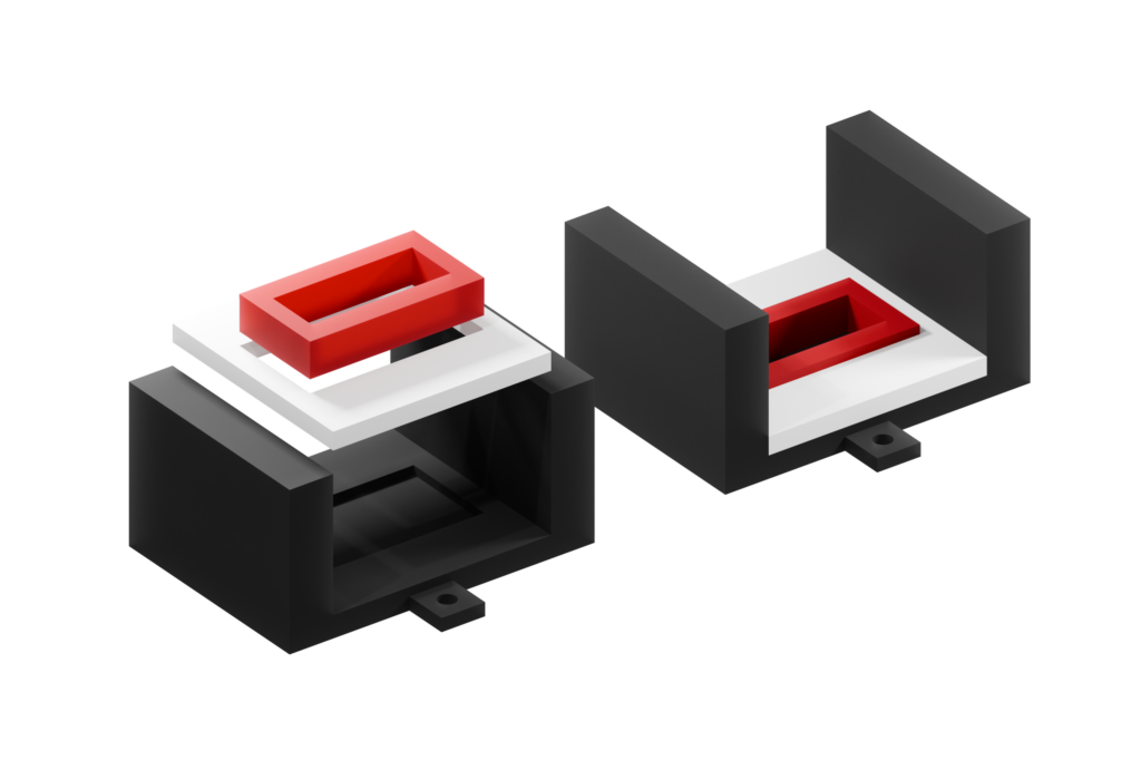
Connect the lining to the structure through the isolation system, with ProSilence channels carrying the board layers.
Explore the component ↗
Floating floors / Support
Bring decoupling into the floor build-up. Plan the support layout and specify the floor structure for the project load.
Explore the component ↗
Between rigid layers / Damp
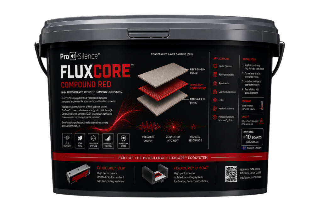
Viscoelastic damping between board layers, used alongside mechanical decoupling as part of the selected build-up.
Explore the component ↗Walls, ceilings and floating floors need their own construction details and relevant test evidence. Airborne wall insulation and floor impact insulation are different measurements.
04 From component to complete room
A working room planner, not a product list. Enter your dimensions, choose the treated surfaces and see calculated component quantities — ready for a discussion with your installer, consultant or local partner.
Preparing the system planner…
05 See it in practice
Explore the technology and see it in practice. Press Play to watch each film here on ProSilence. The embedded YouTube player loads only on request.
Start with the technology at the centre of the system.
A practical demonstration of floor decoupling, not a substitute for a laboratory impact-sound rating.
Explore a studio project using ProSilence and CineVent.
06 European partner development
We are building the European ProSilence partner network. Connect the technology with your local expertise — from specifying the construction to supplying the components and supporting installation.
A focused product family supported by an explanation of the system, technical content and a practical planning tool. Discuss territory, supply and local requirements.
Turn a client's room into an initial component schedule. Share it with the project team and resolve the installation details before ordering.
Review the build-up, examine the low-frequency data and discuss how the system fits your project constraints.